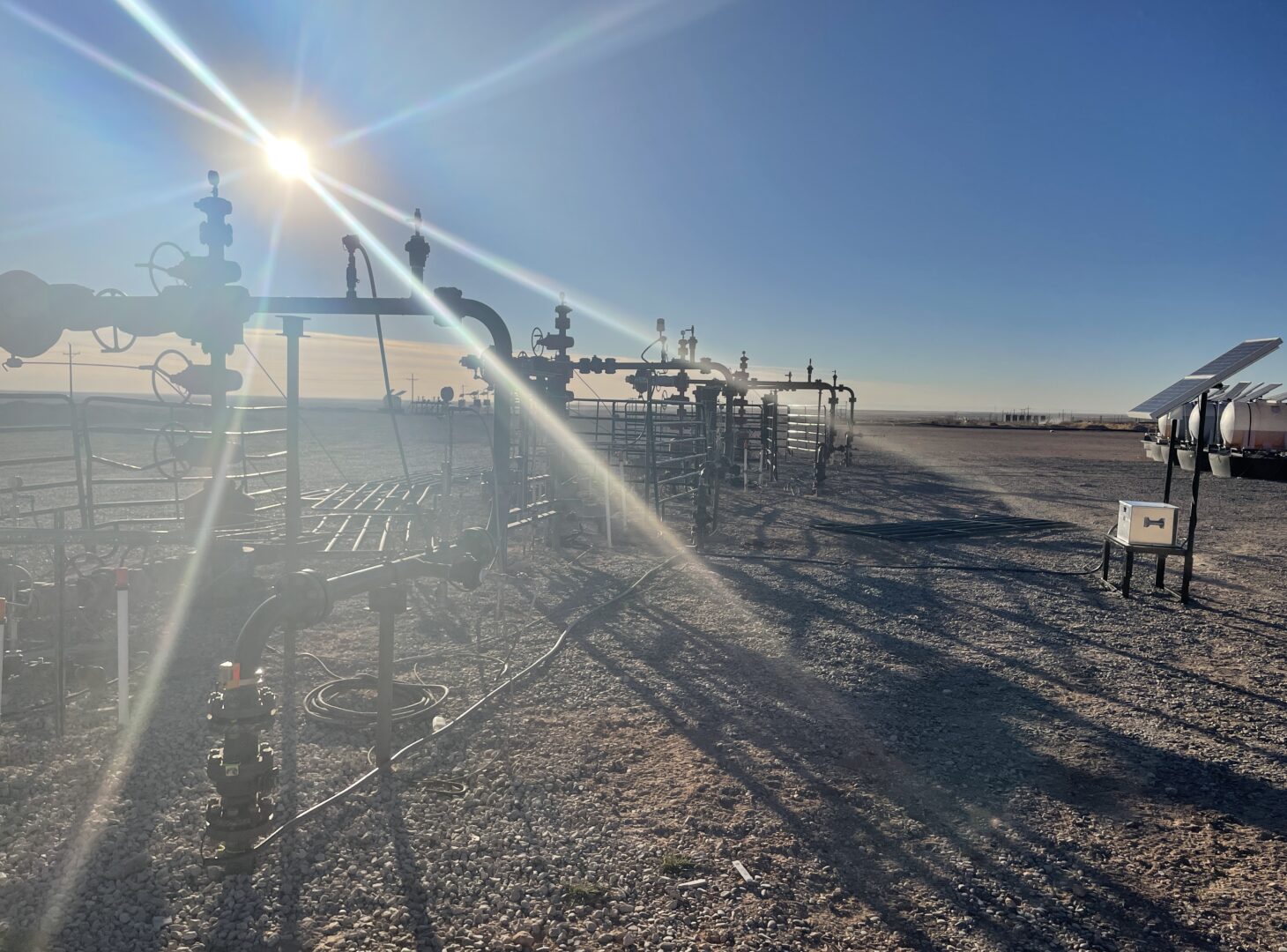
High Temperature Non-Intrusive Monitoring
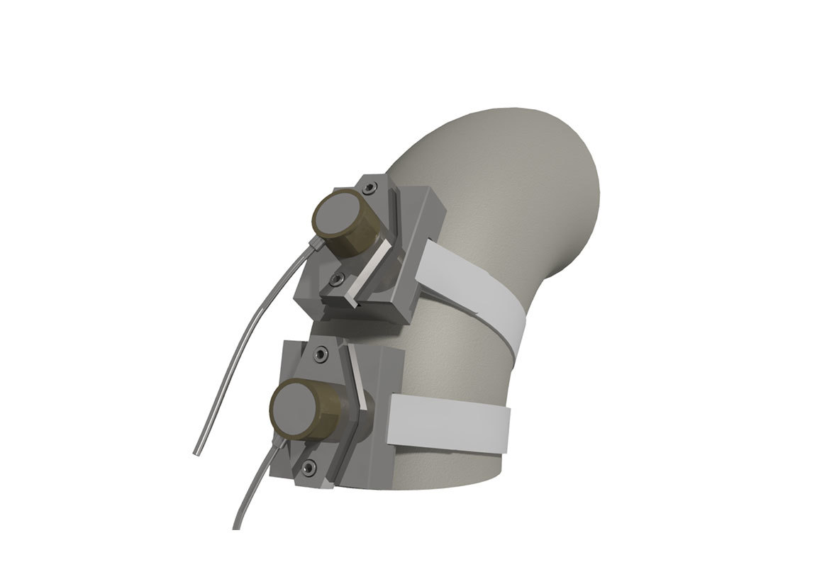
High temperature, non-intrusive wall thickness solutions for in-service corrosion and erosion monitoring. The system comprises of high temperature, ultrasonic transducers, permanently mounted to process pipework, vessels and other structures coupled with a range of instrumentation options from spot reading, through to online, real-time wireless monitoring using industry standard WirelessHART protocol.
Where to Monitor
There are many factors to consider when selecting suitable locations for the installation of Corrosion and Erosion Monitoring and Chemical Injection points. Pipe geometry, flow conditions and process fluid can all influence the occurrence and the development rate of corrosion and erosion within a facility, as well as effecting the rate at which chemicals mix and disperse within the process. The following is therefore intended only to provide additional factors for the site corrosion engineering, and integrity teams to consider when selecting optimum locations for new injection and monitoring installations and should not be used as the sole criteria. In some instances, additional site-specific factors may take priority over the below criteria or prevent the full criteria being met. For these cases it is usually still beneficial to install as close to the optimum criteria as possible.
Corrosion Monitoring Devices
Corrosion monitoring locations should be selected by the plant corrosion engineer / integrity team based on high risk areas identified from previous experience, calculation/simulation or found during manual inspections. Some common examples include:
Multiphase processes, bottom of the line monitoring with flush devices, are typically selected to monitor the water phase as this is often the most corrosive. Similarly, dog legs, and low points are frequently selected for this reason.
Wet gas lines – condensed water can often accumulate at the top of the line causing localised corrosion, particularly in sour service. Flush top of the line devices can therefore be used to monitor for this.
For centre of the line monitoring of horizontal lines, or for monitoring within vertical lines, tubular element probes are often selected. For higher flow rates it is recommended that wake frequency or drag calculations are performed and devices sized accordingly.
Ideally monitoring devices should be installed at a minimum distance of 10x pipe I.D. downstream of any chemical injection point to allow the chemical to mix within the process prior to reaching the probe element.
Additional monitoring points can be located at any point where the process may change such as downstream of branch connections where additional process streams are introduced into the process, and at the end of the line to ensure that chemicals are still effective throughout the piping system.
In instances where more than one method of intrusive monitoring device is used (probe and coupon), access points should be separated as follows:
Flush devices should ideally be a minimum of 1ft apart centre to centre to allow for adequate clearance for online servicing.
Intrusive devices should ideally be located a minimum of 3 x pipe ID apart to account for any turbulence caused by the upstream device.
Erosion Monitoring Devices
Erosion monitoring device locations should be selected based on the highest risk areas determined by the plant corrosion engineering / integrity teams based on previous experience, simulation or areas found during manual inspections.
Locations where the process is flowing at a higher velocity such as downstream of the choke are often considered to have an increased risk for erosion, particularly where the presence of sand has been detected previously or may be suspected/expected. Other areas at high risk for erosion may include locations with rapid changes in direction such as small radius bends, and T-sections.
Generally, ideal locations for intrusive erosion monitoring devices are centre of the line at a minimum of 10 x pipe ID downstream of bends, or T-sections where flow velocity and sand concentration may be higher. As with other intrusive devices, wake frequency/drag calculations can be considered when determining maximum device lengths.
For non-intrusive devices, monitoring locations may include outside radius of bends, and outside and inside of T-sections and at other high velocity areas where the presence of sand may be known or suspected.
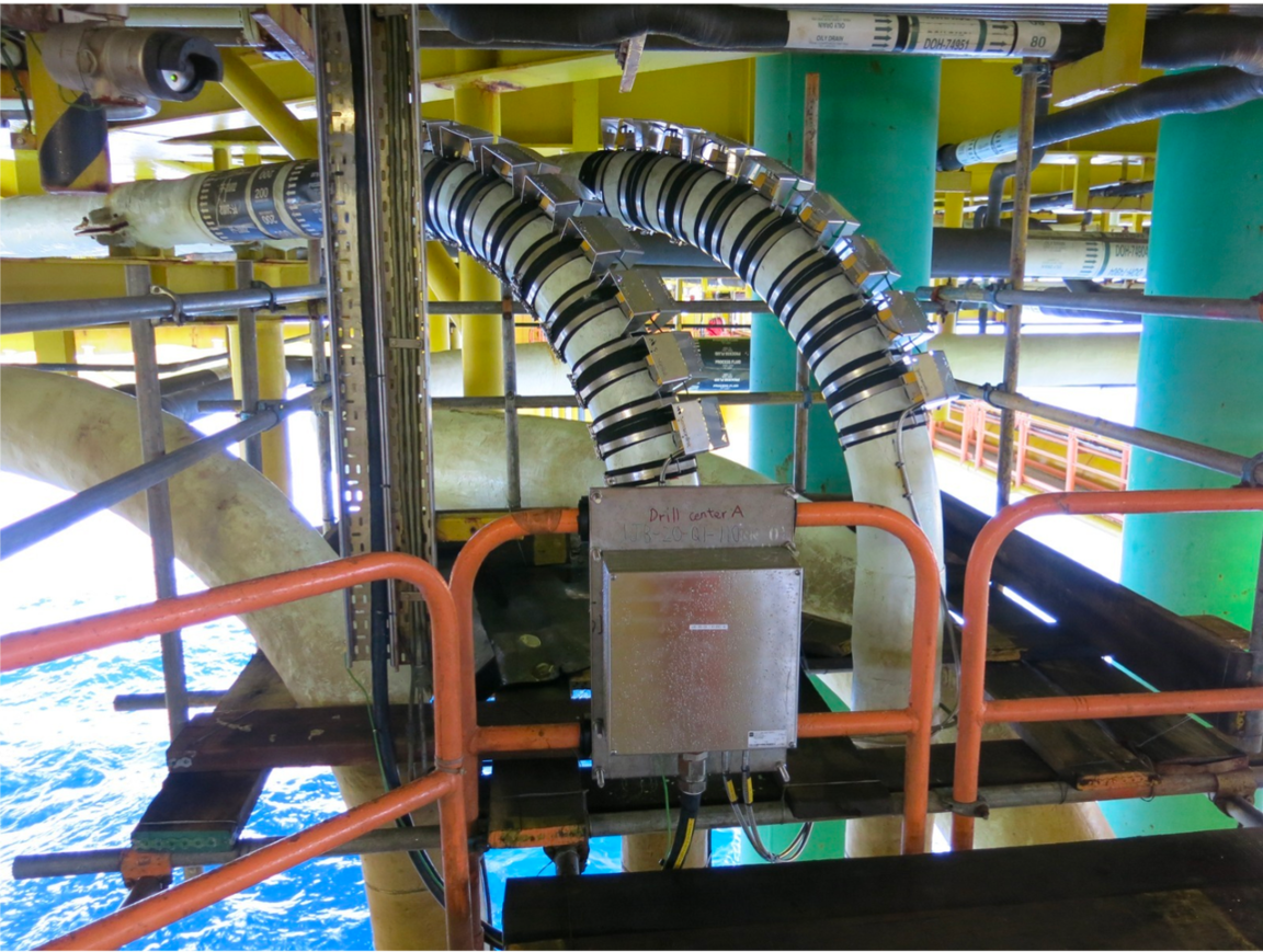
Examples of Where to Monitor on an Upstream Production Facility
- Flow Lines - ER (Corrosion), ER (Erosion), Non-Intrusive (Erosion), Coupons, Biofilm
- Separator Vessels - ER, Non-Intrusive, Coupons
- KO Drums - ER, Non-Intrusive, Hydrogen
- Produced Water / Water Injection - ER, LPR, Galvanic, Non-Intrusive, Biofilm
- Drain Lines - ER, Non-Intrusive, Coupons
- Water Injection - ER, LPR, Galvanic, Non-Intrusive, Biofilm
- Glycol Units - ER, Non-Intrusive, Coupons
- Compression - ER, Non-Intrusive, Coupons
- Flare Lines - ER, Non-Intrusive, Coupons
- Export Lines - ER, Non-Intrusive, Coupons